Universal Gates are logic gates that can be used to implement other gates such as AND, OR and NOT. It can be created to replace for many types of gates when we build a big and complex digital systems. They are two type of universal gates, which are NAND gate and NOR gate.
NAND Gate can be configured to obtain the other common Boolean expressions.
For examples,

|
A
|
B
|
F=(A.B)’
|
|
0
|
0
|
1
|
|
0
|
1
|
1
|
|
1
|
0
|
1
|
|
1
|
1
|
0
|
The output is High(1) when there is at least one of the input is Low(0) and the output is Low(0) when both of the inputs is High(1).
Implementation of NOT, AND, OR and NOR using NAND Gate.
.jpg)
F=A'
Implement as NOT Gate(Hex inverter).
Implement as NOT Gate(Hex inverter).
A NOT gate circuit from a NAND gate simply by tying the two inputs(both High or both Low) of the NAND gate together. If the combination of both inputs are High, the output will be Low and conversely. Thus, the circuit behaves exactly as a NOT gate.
+-+Copy.jpg)
F=(A'.B')'=A.B=AB
Implement as AND Gate
Implement as AND Gate
An AND gate circuit can create by using two NAND gates. The first NAND gate will implement his own function and the second NAND gate invert the output from the first NAND gate and become the output of AND gate.
+-+Copy.jpg)
F=(A'.B')'=A+B
Implement as OR Gate
Implement as OR Gate
An OR gate circuit can create by using three NAND gates. A pair of NAND gates will invert their inputs and the third NAND gate will combine two inputs. If both of the original inputs are Low, then NAND gate will produce Low output. If one/both of the original inputs are High, it will produce High output from the NAND gate.
+-+Copy.jpg)
F=(A+B)'
Implement as NOR Gate
Implement as NOR Gate
An NOR gate circuit can create by using four NAND gates. The circuit is same as the OR gate circuit with an addition of another NOT gate to invert the output from the third NAND gate.
For examples,
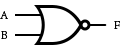
A
|
B
|
F=(A+B)’
|
0
|
0
|
1
|
0
|
1
|
0
|
1
|
0
|
0
|
1
|
1
|
0
|
Implementation of NOT, AND, OR and NAND using NOR Gate.

F=A'
A NOT gate circuit from a NOR gate simply by tying the two inputs(both High or both Low) of the NAND gate together. If the combination of both inputs are Low, the output is High. Otherwise, the output is Low.

F=[(A+B)']'=A+B
An OR gate circuit can create by using two NOR gates. The first NOR gate will implement his own function and the second NOR gates invert the output from the first NOR gate and become the output of OR gate.

Implement as AND Gate
An AND gate circuit can create by using three NOR gates. A pair of NOR gates will invert their inputs and the third NOR gate will combine two inputs. If both of the original input are Low, the NAND gate will produce Low output. If one/both of the original inputs are High, it will produce High output from the third NAND gate.

F=(A.B)'
An NAND gate circuit can create by using four NOR gates. The circuit is same as the AND gate circuit which configured by three NOR gate and another NOR gate configured as a NOT gate to invert the output from the third NOR gate.
No comments:
Post a Comment